Calculation of the Peierls barrier of screw dislocations in bcc metals and its dependence on stress
Source of funding: Czech Science Foundation
Number: P204/10/0255
Duration of funding: 3 years (01/2010-12/2012)
|

|
Main results
Calculation of the Peierls barriers of screw dislocations in BCC metals
We demonstrate that the straightforward application of the Nudged Elastic Band (NEB) method
does not determine the correct Peierls barrier of 1/2<111> screw dislocations in BCC metals.
Although this method guarantees that the states (images) of the system are distributed uniformly
along the minimum energy path, it does not imply that the dislocation positions are distributed
uniformly along this path. In fact, clustering of dislocation positions near potential minima
occurs which leads to an overestimate of both the slope of the Peierls barrier and the Peierls
stress. We propose a modification in which the NEB method is applied only to a small number of
degrees of freedom that determine the position of the dislocation, while all other coordinates of
atoms are relaxed by molecular statics as in any atomistic study. This modified NEB method
with relaxations gives the Peierls barrier that increases smoothly with the dislocation position
and the corresponding Peierls stress agrees well with that evaluated by the direct application of
stress in the atomistic modeling of the dislocation glide.
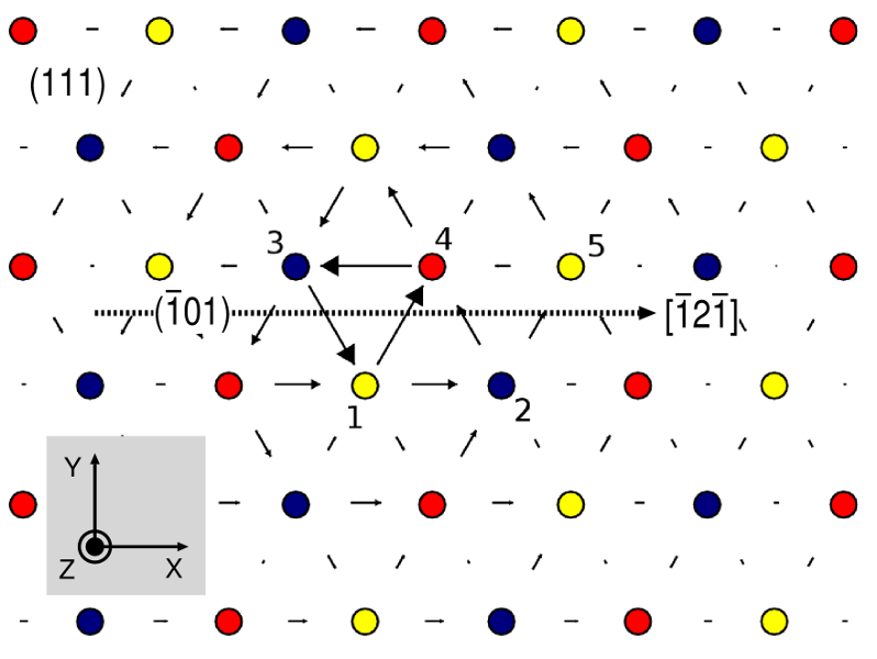
| Fig. 1: The initial image of a block with a 1/2[111] screw dislocation used for the calculation of the
Peierls barrier using the NEB method. The atoms are depicted as circles with the colors that
distinguish the three successive (111) atomic planes.
|
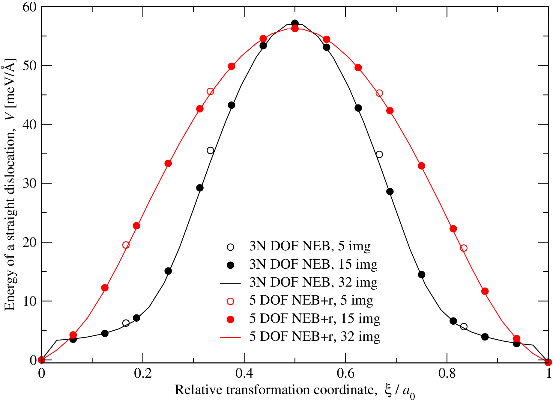
| Fig. 2: Variation of the energy of a straight dislocation along the minimum energy path
between the fixed states at ξ/a0 = 0 and 1, where a0 is the distance of the
two neighboring minimum energy lattice sites in the (101) plane in the [121] direction. The
black data (curve) has been obtained by the standard NEB method that operates in the
configurational space of the dimension 3N . The red data (curve) have been obtained using the
NEB+r method in which only the z coordinates of the five atoms marked 1-5 in Fig. 1 were
adjusted by the NEB force (1), while the remaining DOFs were obtained by atomic relaxations
using the standard molecular statics. In both cases, the barrier is shown to be independent
of the number of images used to discretize the path.
|
We define the transition coordinate ξ as the distance of the dislocation from its position in the
image I=0 to M+1, measured along the path of the dislocation. Unfortunately, the position of the
dislocation cannot be determined unambiguously from the coordinates of all atoms in the block and
thus also the path of the intersection of the dislocation line with the (111) plane is not known
unequivocally. We thus approximate the dislocation path as a straigh line connecting the two neighboring minimum
energy lattice sites, and
a the lattice parameter. This assumption of a straight path of the
dislocation was adopted also by Rodney and Proville (2009), and Ventelon and Willaime (2007). The
variation of the energy of the dislocation, Eq. 2, along this transition coordinate is plotted in
Fig. 2 in black. The same barrier has been obtained when the path of the dislocation was discretized
using M = 5, 15 and 32 images. The barrier increases slowly at first but then rises to its maximum
rapidly. Clearly, this abrupt change of the slope calls for a deeper understanding.
Studies of anisotropic Eshelby twist in thin films of BCC metals
We address the question as to whether the core structure of
screw
dislocations in Mo in the bulk can be
obtained
from
high-resolution
electron microscopy (HREM) images of such dislocations viewed end-on in a thin foil. Atomistic
simulations of the core structure of screw dislocations in elastically anisotropic Mo were carried
out using bond order potentials. These simulations take account automatically of the effects of the
surface relaxation displacements (anisotropic Eshelby twist). They show that the differential
displacements of the atoms at the surface are different with components perpendicular to the Burgers
vector about five times larger than those in the middle of the foil, the latter being characteristic
of the bulk. Nye tensor plots show that the surface relaxation stresses strongly affect the
incompatible distortions. HREM simulations of the computed structure reflect the displacements at
the exit surface, modified by interband scattering and the microscope transfer function. Nye tensor
plots obtained from the HREM images show that interband scattering also affects the incompatible
distortions.
Since the HREM image reflects the displacements at the exit surface, the fundamental questions are:
- Whether the HREM observations relate to the core displacements in the bulk.
- Whether the stresses associated with the Eshelby twist produce such significant changes in the dislocation core
structure that the relation to the core structure in the bulk becomes obscured.
The objectives of this work have been to elucidate these points by carrying out an atomistic simulation
of the 1/2[111] screw dislocation in a thin foil of Mo of thickness typical for HREM observations,
and to simulate the HREM images of the calculated structure. The atomic displacements of the relaxed
structure automatically contain the surfaceinduced relaxation displacements, and the effects of the
surface relaxation stresses on the core structure. These displacements can then be identified as the
difference between the relaxed positions of atoms in the foil and their relaxed positions in a block
that is periodic in the direction parallel to the dislocation line, i.e. without free
surfaces. Finally, the calculated relaxed atomic positions in the foil can be used as input for the
image analysis. This provides the positions of image peaks at the exit surface, which reflect the
Eshelby twist and core displacements, plus the displacements due to the interband scattering and the
microscope transfer function.
| 
| 
|
| (a)
| (b)
| (c)
|
|
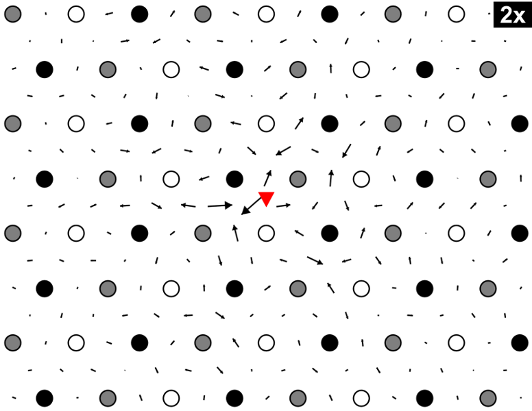
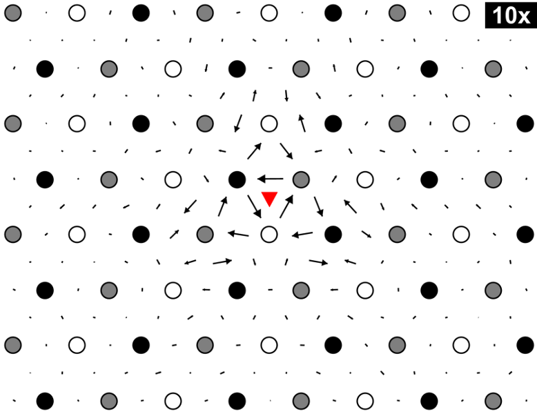
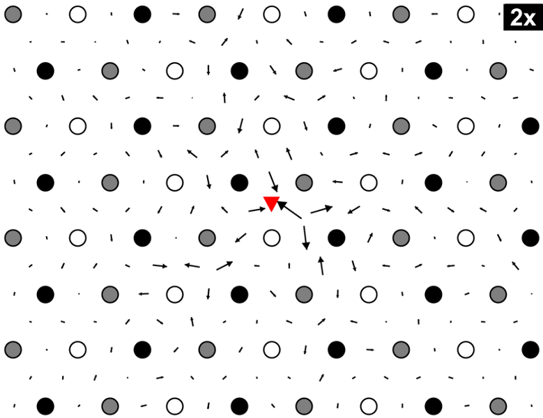
Fig. 1: Map of edge differential displacements for the 1/2[111] screw dislocation calculated
for three slices taken from the block representing the foil at (a) z=+h/2 (upper surface),
(b) z=0 (centre of the foil), and (c) z=-h/2 (lower surface). The displacements in (b) are
scaled by a factor of 10 whereas those in (a) and (c) by a factor of 2.
|
Fig. 1 shows the maps of the differential displacements perpendicular to the dislocation line (and to
the Burgers vector) for three slices taken from the upper and lower surfaces and from the center of
the relaxed block that represents the foil. The atomic arrangement is shown in the projection
perpendicular to the direction of the dislocation line. The circles stand for the atoms in the three
consecutive (111) atomic planes (differentiated by shading) and the lengths of the arrows are
proportional to the magnitudes of the relative displacements of neighboring atoms in the direction
perpendicular to the dislocation line, i.e. corresponding to the relative displacements in the z
direction and in the (x,y) plane, respectively. The colors of atoms are chosen such that they get
darker with increasing position along the z direction in the ideal lattice. The edge displacements
near the surfaces are about five times larger than those in the centre of the foil and, therefore,
the displacements in Fig. 1b are scaled by a factor of 10, whereas those in Figs. 1a and 1c only
by a factor of 2.
|
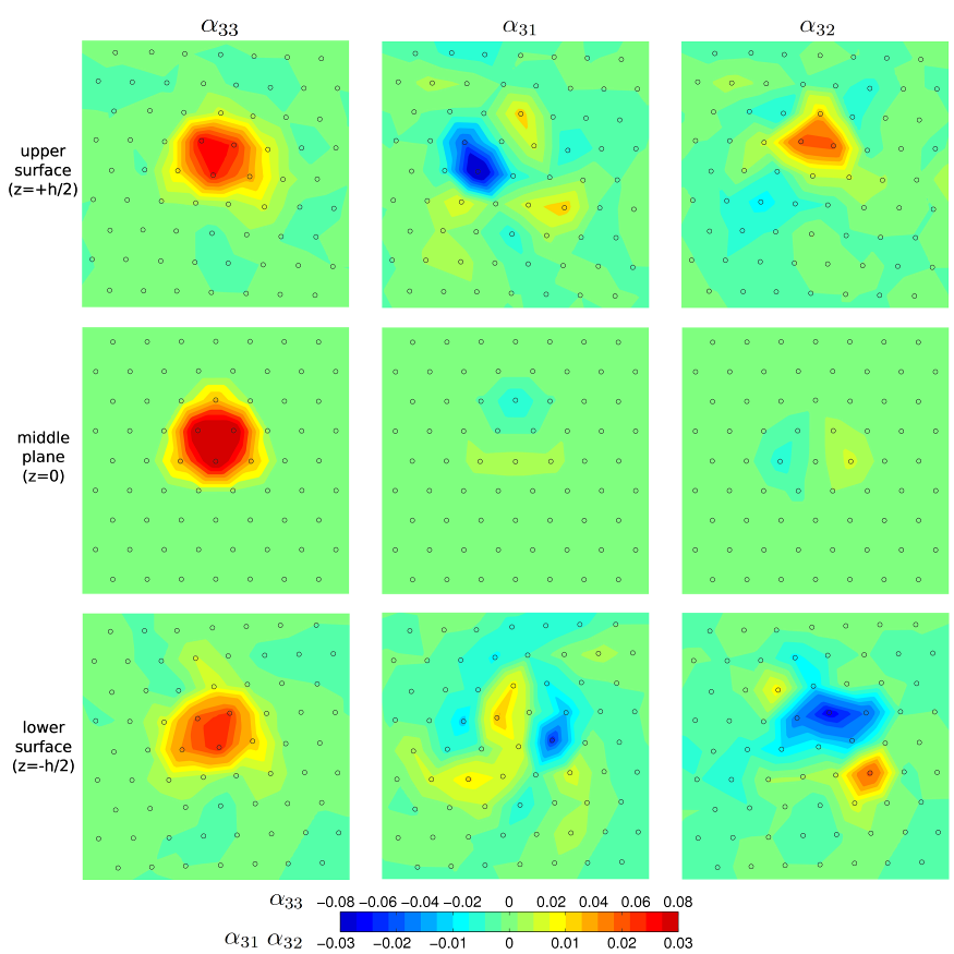
Fig. 2: Plots of Nye tensor components for three slices taken from the upper (z=+h/2) and
lower surfaces (z=-h/2) of the foil and from the middle of the foil (z=0). The colors correspond to
the density of the Burgers vectors of continuously distributed infinitesimal dislocations. The
component σ33 corresponds to the screw component; σ31 and
σ32 to the two edge components parallel to the x and y axes, respectively. The
circles represent the relaxed positions of atoms in the three consecutive (111) planes.
|
Any compatible distortion of the lattice for which the displacement field remains single-valued and
the strain field integrable does not affect the Nye tensor. Consequently, if the Eshelby twist did
not affect the dislocation core, the Nye tensor plots calculated for the two surface slices would
have to be identical to that taken from the middle of the foil. In Fig. 2 we show the three relevant
components of the Nye tensor for the upper and lower surfaces and the middle of the foil. Since the
dislocation line is parallel to the z direction, α
33 corresponds to the screw
component of the dislocation density. Similarly, α
31 and α
32
relate to the two edge components, for the Burgers vectors parallel to x and y, respectively. We
represent the dislocation core by a region around the dislocation in which the displacements of
atoms relative to their positions in the ideal lattice, and thus also α
ij, are larger than some
threshold. Since the Eshelby twist strongly affects the edge component of this field (as seen in
Fig. 2), i.e. the relative displacements of atoms perpendicular to the slip direction, the
dislocation core close to the two free surfaces is very different from that in the centre of the
foil. We thus conclude that the Eshelby twist strongly affects the dislocation core near the foil
surfaces but not in the bulk of the foil. The Eshelby twist thus induces both compatible deformation
away from the dislocation core and the incompatible deformation in the core region.
Dissemination of results
Impact papers
- Gröger R., Vitek V.:
Stress dependence of the Peierls barrier of 1/2<111> screw dislocations in BCC metals.
Acta Mater. 61:6362-6371 (2013).
- Srivastava K., Gröger R., Weygand D., Gumbsch P.:
Dislocation motion in tungsten: Atomistic input to discrete dislocation simulations.
Int. J. Plast. 47:126-142 (2013).
- Gröger R., Vitek V.:
Constrained Nudged Elastic Band calculation of the Peierls barrier with atomic relaxations.
Model. Simul. Mater. Sci. Eng. 20:035019 (2012).

- Gröger R., Dudeck K.J., Nellist P.D., Vitek V., Hirsch P.B., Cockayne, D.J.H.:
Effect of Eshelby twist on core structure of screw dislocations in molybdenum:
Atomic structure and electron microscope image simulations.
Philos. Mag. 91:2364 (2011).
Papers in conference proceedings
- A new approach to calculate the Peierls barrier of screw dislocations in BCC metals. Int. Symp. on
Plasticity and Its Current Applications, San Juan, Puerto Rico (January 3-8, 2012).
Invited talks
- A new approach to calculate the Peierls barrier of screw dislocations in BCC metals. Int. Symp. on
Plasticity and Its Current Applications, San Juan, Puerto Rico (January 3-8, 2012).
Contributed talks
- Atomistic calculation of the Eshelby twist in BCC metals. University of Oxford, Oxford, UK (April 29-30, 2010).
Conferences and workshops
- Member of the International Advisory Committee, International Conference on Plasticity (2012).
- Co-organizer of a minisymposium "Plasticity of BCC metals" at the Int. Symp. on
Plasticity and Its Current Applications, San Juan, Puerto Rico (January 3-8, 2012).
Prizes and awards
- Otto Wichterle prize "for outstanding young researchers of the Academy of Sciences of the
Czech Republic", Academy of Sciences of the Czech Republic (2010)